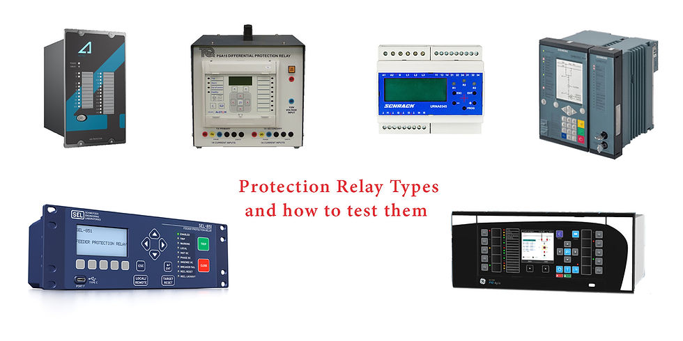
Protection Relay Types and Corresponding Testing Procedures
- EnergyTesting

- Sep 13, 2024
- 5 min read
In the current grid network you'll find millions, if not billions, of protection relays installed. They serve one of the main purposes - keep operation and power supply as smooth and stable as possible, and protect the assets and remaining grid as fast as possible when needed.
To know exactly how to test them, and what is needed for this in one case or another, let's define and classify them firstly.
Protection relays are categorized based on their construction, operation, and application.
Protection Relays Types
By design type
1. Electromechanical Relays
Function: Operate using electromagnetic forces to physically move contacts.
Application: Used for basic protection in legacy systems, such as overcurrent, distance, and differential protection.
Key Features: Reliable, but bulky and prone to wear over time.
2. Solid-State Relays
Function: Utilize electronic components, like transistors and diodes, to perform switching.
Application: Provide overcurrent, undervoltage, and frequency protection in various power systems.
Key Features: More reliable than electromechanical, with no moving parts.
3. Microprocessor-Based Relays (Digital/Static Relays)
Function: Employ microprocessors to process inputs and perform protective functions through software algorithms.
Application: Multi-functional, handling overcurrent, distance, differential, and more, with precise settings.
Key Features: Programmable, offering greater accuracy, flexibility, and the ability to store data for diagnostics.
By application type
1. Overcurrent Relays
Function: Activate when current exceeds a preset level.
Application: Protect against short circuits and overloads.
Types: Instantaneous, inverse time, and definite time overcurrent relays.
2. Distance Relays
Function: Measure impedance and operate based on the distance from a fault location.
Application: Typically used for transmission line protection.
Types: Impedance, reactance, and mho relays.
3. Differential Relays
Function: Compare current between two or more points and operate if the difference exceeds a threshold.
Application: Protect transformers, generators, and busbars.
Types: Current differential, voltage differential.
4. Directional Relays
Function: Sense the direction of current flow and operate based on fault direction.
Application: Used in systems where power flow direction needs to be controlled, such as feeders and tie lines.
5. Undervoltage and Overvoltage Relays
Function: Operate when the voltage falls below or rises above a set level.
Application: Used to protect against undervoltage and overvoltage conditions in electrical systems.
6. Underfrequency and Overfrequency Relays
Function: Monitor system frequency and operate if it deviates from the acceptable range.
Application: Used in generator protection and grid frequency control.
Each type of relay plays a critical role in ensuring the safe operation and protection of electrical power systems.
Protection relay testing is essential for ensuring that relays perform correctly and respond as expected during electrical faults. The testing procedures vary based on the type of relay, but generally, they include visual inspections, functional tests, and performance validation. Below are the key tests:
Protection Relay Testing Procedures
1. Visual and Mechanical Inspection
Purpose: To ensure the relay is in good physical condition and properly installed.
Steps:
Inspect the relay for any physical damage, loose connections, or signs of wear.
Verify that all wiring is correct according to the relay and protection scheme diagram.
Check for proper relay mounting and grounding.
Confirm the cleanliness of the relay, ensuring no dust or debris that could affect operation.
2. Insulation Resistance Test
Purpose: To check the insulation integrity of the relay and its wiring.
Steps:
Use an insulation resistance tester (megger) to measure the resistance between the relay terminals and ground.
Compare measured values against manufacturer-recommended insulation resistance levels.
High insulation resistance indicates good insulation, while low resistance points to potential faults.
3. Operational (Functional) Testing
Purpose: To verify the proper functioning of each relay element in the protection scheme.
Steps:
Simulate various fault conditions by applying test signals (voltage, current, or frequency) through a secondary injection test set.
Check the relay’s response time and ensure that it trips or sends appropriate signals when thresholds are exceeded.
For microprocessor-based relays, verify digital display readings, event logs, and communication protocols.
Validate each relay element (overcurrent, differential, distance, etc.) independently to ensure correct operation.
4. Secondary Injection Testing
Purpose: To simulate actual system conditions and ensure the relay responds correctly to applied test signals.
Steps:
Apply a known current or voltage into the relay's secondary side (from the CTs or VTs).
Adjust settings to simulate fault conditions such as overcurrent, under/over voltage, or phase imbalances.
Measure the relay’s operating time and compare it to specified values.
Ensure the relay triggers the appropriate trip signal or alarm.
Record and document all test results for analysis.
5. Primary Injection Testing
Purpose: To test the entire protection system, including CTs, cables, and relay circuits, by injecting a current or voltage directly into the primary system.
Steps:
Connect a high-current primary injection test set to the main circuit.
Inject current through the primary side of the CT to simulate fault conditions.
Observe the relay’s operation and trip the circuit breaker if necessary.
Verify the correct operation of the relay in real-time, along with associated tripping devices.
6. Contact Resistance Test
Purpose: To measure the resistance of the relay’s contacts and ensure low resistance for reliable performance.
Steps:
Apply a low current (typically 100A or more) across the relay contacts.
Measure the voltage drop across the contacts and calculate the resistance using Ohm’s law.
Compare the measured resistance with the manufacturer’s specifications to determine contact condition.
7. Time-Current Characteristic (TCC) Testing
Purpose: To confirm that the relay operates within the time-current characteristic (TCC) curve specified by the manufacturer.
Steps:
Apply increasing levels of current or voltage while recording the relay’s response time.
Plot the results on a TCC curve to verify the relay's behavior under various fault levels.
Ensure that the relay operates within the prescribed time limits for each fault scenario.
8. Pickup and Dropout Testing
Purpose: To check the pickup and dropout points of the relay and ensure proper operation at the desired setpoints.
Steps:
Gradually increase the test current/voltage until the relay activates (pickup point).
Slowly reduce the test current/voltage until the relay resets (dropout point).
Verify that the pickup and dropout points align with the relay settings and manufacturer specifications.
9. Trip Circuit Supervision Test
Purpose: To ensure the integrity of the trip circuit, including the wiring, trip coil, and relay output contacts.
Steps:
Test the continuity of the trip circuit to verify that all connections are intact.
Simulate a fault condition and check if the relay successfully sends a trip signal.
Confirm that the breaker operates correctly upon receiving the trip signal.
10. Relay Settings Verification
Purpose: To confirm that the relay is configured according to the required protection settings.
Steps:
Review the relay’s settings, including pickup levels, time delays, and protection functions.
Compare the configured settings with the protection scheme documentation.
Make any necessary adjustments to match the system requirements.
11. End-to-End Testing
Purpose: To validate the performance of protection relays across different substations by testing the entire protection scheme, including communication links.
Steps:
Use synchronized test equipment to simulate faults across the network.
Test the communication between relays in different locations to ensure correct fault detection and coordination.
Verify that the relays operate as expected under real-world fault conditions.
12. Event Recording and Analysis
Purpose: To review and analyze relay behavior during testing or actual fault events.
Steps:
Access the event logs and disturbance records from the relay (for digital relays).
Analyze the event data to assess relay performance and response time.
Use the data to adjust settings, if necessary, or improve fault coordination.
13. Final Reporting and Documentation
Purpose: To provide a comprehensive record of relay testing, including test results and any adjustments made.
Steps:
Document all test procedures, results, and relay settings.
Include any corrective actions taken or settings changes made.
Maintain records for future reference and relay performance tracking.
Conclusion
Protection relay testing is critical to ensuring the reliability and safety of electrical power systems. Following a structured procedure that includes visual inspections, functional tests, and performance validation helps identify issues before they lead to equipment failures or outages. Regular testing and maintenance also ensure compliance with system protection requirements and improve overall system reliability. To make life easier some relay test sets already provide you an option ot generate automatic assesment report after the test is performed.


Did we forget about something? Join the conversation and share your thoughts to improve this guide!