Difference Between Relay and Circuit Breaker and their applications
- EnergyTesting

- May 23, 2025
- 3 min read
Updated: May 28, 2025
In the world of electrical engineering, relays and circuit breakers are often mentioned in the same breath. Both are vital to the protection and control of electrical systems, but their functions, designs, and roles within the system are fundamentally different. Understanding this distinction is not only academically interesting—it is critical for professionals who are responsible for designing, testing, and maintaining protection systems in substations and industrial environments.
What is a Relay?
A relay is essentially a decision-making device. It monitors electrical quantities—such as current, voltage, frequency, or phase angle—and responds when predefined thresholds are crossed. Once it detects an abnormal condition, such as an overcurrent or earth fault, it sends a trip command to another device—the circuit breaker. In essence, a relay does not interrupt the circuit itself; rather, it signals that an interruption should occur.
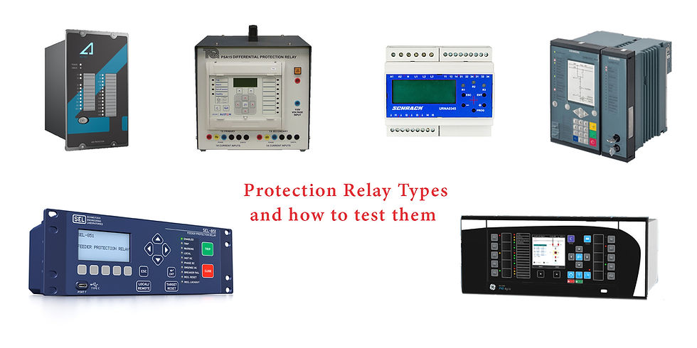
There are several types of relays used in protection schemes, including electromagnetic relays, static relays, and the increasingly dominant numerical relays. All of these require routine validation, as incorrect settings or performance drifts can have catastrophic consequences. That's why a Protection relay tester is a key tool in any technician’s arsenal. It allows engineers to simulate fault conditions and verify that the relay operates correctly and within the required time frames. Without proper relay testing, even the most robust system can become vulnerable.
What is a Circuit Breaker?
The circuit breaker, in contrast, is the muscle of the operation. When the relay decides a fault has occurred and sends the trip command, the circuit breaker physically opens the circuit to stop the flow of current. This interruption isolates the faulted section, protecting equipment and ensuring safety. Unlike a fuse, which sacrifices itself to interrupt a fault, a circuit breaker is designed to open and close repeatedly without sustaining damage.
Circuit breakers are categorized by their voltage levels and arc-quenching mechanisms: air, SF6, vacuum, and oil are common types. In all cases, testing their operation under simulated fault conditions is critical. A Circuit breaker tester ensures that the breaker responds correctly to trip signals and can handle real-life fault currents without failure.

The performance of a breaker is not only about whether it opens, but how quickly and in what sequence. Delays of milliseconds can mean the difference between a contained fault and widespread equipment failure. Proper commissioning and periodic maintenance with reliable test sets is therefore essential for utilities and large-scale industrial operators.
Feature | Relay | Circuit Breaker |
Function | Senses abnormal conditions and sends a trip command | Executes the trip command by physically interrupting the circuit |
Operation | Works with low-energy control signals | Operates high-power switching mechanisms |
Role | Monitoring, detection, decision-making | Isolation and physical circuit interruption |
Type of Action | Indirect – triggers other devices | Direct – opens the circuit |
Response Time | Fast (milliseconds), depends on configuration | Also fast, but response is mechanical and depends on actuator |
Test Equipment Used |  |  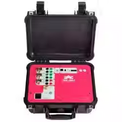 |
Common Types | Electromechanical, Static, Numerical | Air, Vacuum, SF6, Oil |
Failure Impact | Missed detection or false alarms | Incomplete fault clearing, potential system damage |
Maintenance Needs | Calibration, logic testing | Mechanical inspection, contact wear analysis |
System Test Tools | Logic analyzers, test sets, Primary injection kits | Timing analyzers, motion analyzers, Primary injection kits |
How They Work Together
The relay and circuit breaker form a cohesive protection system. The relay continuously monitors for faults, while the circuit breaker waits, ready to act upon the relay’s instruction. When a fault occurs, the relay makes the judgment call, and the breaker executes the command.
This coordinated operation must be validated not only in isolation but also as a system. This is where the Primary injection kit comes into play. By injecting high currents into the system, it allows engineers to test the actual behavior of the protection chain under realistic conditions—from the sensing CTs through to the relay logic and the actuation of the breaker. These end-to-end tests are critical for verifying that timing coordination, sensitivity, and communication pathways are functioning as intended.
Practical Implications
In the field, the difference between relays and breakers becomes starkly apparent. If a relay fails to detect a fault, or if the breaker fails to open when told to, the result can be catastrophic: damaged transformers, lost production, or even dangerous arc flashes. That’s why modern protection systems are rigorously designed and thoroughly tested using the tools mentioned above.
Testing is not a one-time event but a continuous process. Relays can drift out of tolerance; breakers can develop mechanical wear or slow operation times. By employing a combination of protection relay tester and a switchgear tester on a regular maintenance schedule, asset owners can ensure system integrity. When high-fidelity system-level validation is required—such as during commissioning or after significant modifications—automatic solutions provide the most comprehensive picture.
While both relays and circuit breakers serve protective functions, their roles are not interchangeable. The relay is the intelligent detector and decision-maker; the circuit breaker is the executor of that decision. Neither can function effectively without the other, and both require regular, accurate testing to ensure reliability.


Comments